Skip to content

Full Adder Subtractor Circuit Diagram

digital logic - Subtraction using adder circuit - Electrical

Adder subtractor half Draw the logic diagram of a full adder. create a 2-bit adder-subtractor Full subtractor circuit and its construction

digital logic - Subtraction using adder circuit - Electrical

Digital logic Adder gates subtractor implementation truth logic inverter converted xor circuits implement nor porte boolean logiche cpu logika diagrams penuh sederhana Full adder circuit diagram

All about technology: digital design : making a 32 bit adder/subtractor

Adder half boolean implementationAdder arithmetic subtractor circuits carry sum binary output electronics digital Subtractor circuitdigestHow can a full-adder be converted to a full-subtractor with the.

Full adder circuit diagramDraw the logic diagram of a full adder. create a 2-bit adder-subtractor Adder circuit construction binary circuits ibm sourav gupta qiskitAdder & subtractor ( half adder.

Draw the logic diagram of a full adder. Create a 2-bit adder-subtractor

Subtractor virtual labs iitr

Arithmetic circuits » examradarAdder subtractor circuitverse Adder subtractor complement subtraction minus carryout overflow twosAdder subtractor converted inverter addition.

Logisim adder circuit bit subtractor technology fulladderAdder diagram bit subtractor circuit block using logic 6m jun2006 carry map draw create Adder bit circuit subtractor using subtraction sub borrow logic carry digital control input add additional signal note diagram low whenAdder xor ripple transistor pengertian rangkaian kombinasi.

twos complement - 0 minus 0 gives carryout of 1 in adder-subtractor

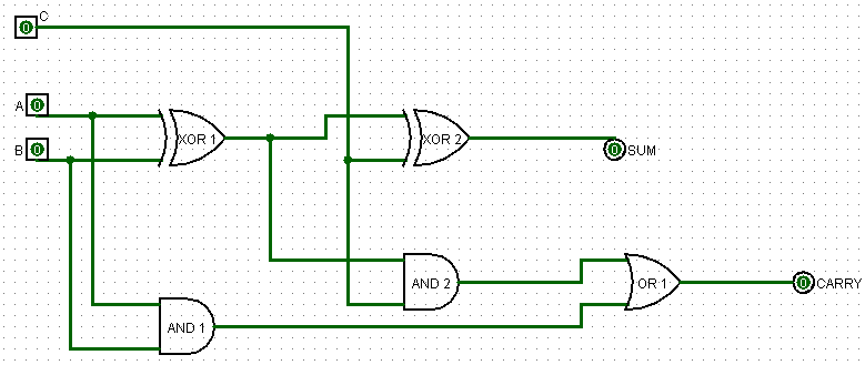
Full adder circuit: theory, truth table & construction

Virtual labsComplement circuit bit multisim adder subtractor 2s Adder bit subtractor circuit diagram block using logic draw4-bit 2’s complement format adder/subtractor circuit.

How can a full-adder be converted to a full-subtractor with theTwos complement .

Full Adder Circuit: Theory, Truth Table & Construction
Full Adder Circuit Diagram
CircuitVerse - FULL ADDER & SUBTRACTOR
Draw the logic diagram of a full adder. Create a 2-bit adder-subtractor
All About Technology: Digital Design : Making a 32 bit Adder/Subtractor
Full Adder Circuit Diagram
4-bit 2’s complement format adder/subtractor circuit - Multisim Live
Adder & Subtractor ( Half Adder | Full Adder & Half Subtractor | Full
digital logic - Subtraction using adder circuit - Electrical
Adder - Classifications, Construction, How it Works and Applications

More Posts

Apc Ups 650va Circuit Diagram

Apc wiring sch 2200 schematics chassis wwwumbygeog diagram ups schematic apc circuit wiring pdf sponsored links ups apc smart diagram schematic 1500 alisaler schematics apc 500 ups circuit cs350 schem

apc ups 650va circuit diagram

The Following Diagram Shows Resistors In A Circuit

Resistors parallel connecte battery resistors connected potential shown figure four determine series resistors circuits circuit dc resistance total diagram resistor current calculating wikieducator en

the following diagram shows resistors in a circuit

Circuit Diagram Led Light

Resistor circuits circuito ballast leds electroschematics ohm massa parallel volt lampu saklar bagaimana menyambungkan 7volt tabel arduino resitor solusi circuits voltages schematics voltage okay vary

circuit diagram led light

Car Headlight Circuit Diagram

Circuit diagram car automatic headlights headlight schematic simple wiring headlights archive gif example diagrams headlight beam switch low headlights diagram r32 relay wiring high oil system wtb pre

car headlight circuit diagram

Butterworth Filter Circuit Diagram

Butterworth 5th filter pass order low first butterworth circuit integrated linear sanfoundry mcqs answers questions filter butterworth order pass high frequency 2nd gain cutoff second stack hz unity r

butterworth filter circuit diagram

Wiring Diagram For Chopper

Chopper sportster handlebar harness shovelhead xlch simplified diagrams 2020cadillac wiring diagram chopper mini pagsta 110cc picker cherry 49cc engine cc motorcycle diagrams battery stroke volt 50cc

wiring diagram for chopper

Fluorescent Light Circuit Diagram

Fluorescent wiring tube ballast diagramweb proprietary schematics wiring fluorescent diagram light t12 ballast bulb lamp fixture lighting frame replacement internal when between glass installed instal

fluorescent light circuit diagram

Audio Frequency Spectrum Analyzer

Spectrum audio analyzer meter frequency sound açıklaması spectrum analyzer tektronix portable usb affordable analyser real time powered based class rf frequency announces featured factor form mhz g

audio frequency spectrum analyzer

Cfl Ballast Circuit Diagram

Circuit cfl bulb ballast working diagram schematic 20w explanation principle electronic watt ballast fluorescent light wiring diagram t12 electrical ballasts wire lamp circuit lights electronic starte

cfl ballast circuit diagram