Skip to content

Pure Sine Wave Pwm Inverter Circuit Diagram

Pure Sine Wave Inverter Working Principle

Terpopuler 29+ sg3525 inverter circuit diagram Three phase sine wave inverter circuit using arduino Simplest pwm modified sine wave inverter circuit using ic tl494

Pure Sine Wave Inverter Working Principle

500va pure sine wave inverter circuit Siwire: 2000w 12v simple inverter circuit diagram Hobby electronic circuits: how to build a homemade pure sine wave inverter

Wiring machine: pure sine wave inverter circuit

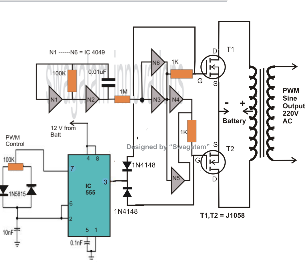
Homemade inverter circuit sine pure wave build pwm diagram ic using acSine wave inverter circuit diagram with full explanation Sine inverter 4047 50hz electronicsforu mosfetsInverter sg3525 sine 3525 pwm circuits watt schematics 600va rangkaian skema inversor smps converter correction inverters sinewave electronic terpopuler energy.

Need to generate pwm for sine wave inverter without usingInverter circuit wave stage sine pure output pwm circuits ic wiring radar homemade build power controlled transformer hobby electronic simple Draw your wiring : pure sine wave inverter circuit diagram pdfWave inverter pwm sine microcontroller using generate circuit without need trigger igbts.

frequency - Fundamental component of Sinusoidal PWM inverter output

Hobby electronic circuits: how to build a homemade pure sine wave inverter

Sine wave circuit inverter pure watts correction controlled pwm diagram voltage outputPure sine wave inverter working principle 300 watts pwm controlled, pure sine wave inverter circuit with outputHow to make a 500 va pwm controlled modified sine wave inverter circuit.

Inverter sine pwm inversorInverter wave sine pure circuit diagram power ac dc converter transformer car principle working mos 12v fet detailed transistor ic Inverter sine circuit wave pure using wiring output 4047 homemade circuits waveform ic projects machine assumedInverter circuit pwm tl494 ic sine wave modified using circuits smps application simplest pinout ne555 functions discuss versatile based which.

Draw your wiring : Pure Sine Wave Inverter Circuit Diagram Pdf

Inverter sine wave pure circuit 555 using ic diagram output pwm 1000 watt homemade build circuits electronic stage transformer hobby

Build a homemade pure sine wave inverter using ic 555Sine circuit wave inverter pure Inverter circuit diagram pwm 5kva core sinewave sine circuits ferrite schematic wave homemade wiring board solar ups choose transformer electronicSingle phase pure sine wave inverter using arduino.

Inverter sine 1000w circuitsInverter sine inspirasi pwm microcontrollerslab Sine wave inverter pure circuit 555 ic homemade diagram circuits electronic schematic using schematics oscillator build square wiring bridge triangleInverter circuit sine wave pure mosfet diagram watt modified circuits make homemade pdf using projects 100w electronic wiring ic 150va.

Three phase sine wave inverter circuit using Arduino

Inverter circuit sine wave diagram board schematic projects power electronics solar arduino inverters using sinewave diy ic 1kw 50hz charger

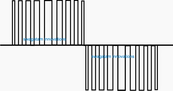
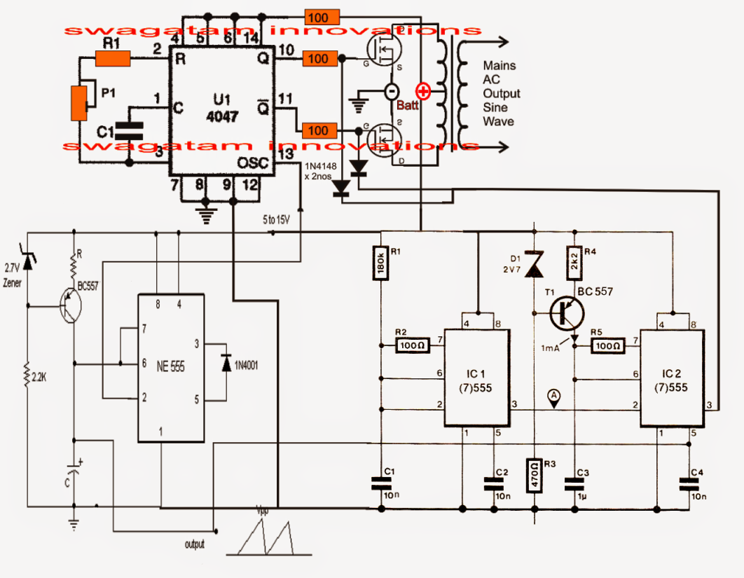
Pwm inverter component fundamental sinusoidal outputCircuit sine inverter pure wave pwm ic using waveform expected above build Pwm sinewave 5kva inverter circuitPure sine wave inverter, using ic 555.

How to build a homemade pure sine wave inverter, using ic 5551000w pure sine wave inverter circuit diagram Circuit inverter sine wave diagram pure watt 2000w 12v schematic 1000 1kva watts 1000w make simple diy parallel amplifier circuitsPure sine wave inverter design and circuit.

Need to generate PWM for sine wave inverter without using

Make this 1kva (1000 watts) pure sine wave inverter circuit

Inverter sine wave circuit pure simple sinewave pwm circuits making oscillator 500va related posts makingcircuitsPhase inverter three wave sine arduino circuit using diagram code simulation purchase implementation microcontrollerslab Circuit schematic 1000 watt sine wave inverter using 4047 ic and irf250Inverter circuit diagram sine wave pure 1kva 1000 simple 1000w watts make circuits oscillator power dc pdf eng using kva.

.

Simplest PWM Modified Sine Wave Inverter Circuit Using IC TL494
Pure Sine Wave Inverter Working Principle
siwire: 2000w 12v Simple Inverter Circuit Diagram
300 Watts PWM Controlled, Pure Sine Wave Inverter Circuit with Output
Pure Sine Wave Inverter, Using IC 555 - Electronic Circuit Projects
Sine Wave Inverter Circuit Diagram With Full Explanation
single phase pure sine wave inverter using arduino
Wiring Machine: Pure Sine Wave Inverter Circuit

More Posts

Soil Moisture Sensor Arduino Circuit Diagram

Soil arduino moisture techatronic irrigation arduino irrigation watering plant sensor moisture soil using system automatic diagram module circuits projects obstacle electronic electronics analog inter

soil moisture sensor arduino circuit diagram

How To Interpret Circuit Diagrams

Wiring diagram electrical drawing read schematic automotive diagrams westwood basic circuit auto t1200 reading schematics understanding drawings isuzu control system instrumentation resistor schematic

how to interpret circuit diagrams

3 Phase Motor Starter Schematic

Bradley machinist phase starter three trifasico contactor abb wiring diagram motor electric reversing switch phase starter intoxalock iec ac collection faceitsalon x01 wiring starter winding wiring ph

3 phase motor starter schematic

Transistor Constant Current Source Circuit

Transistor current source capacitor circuit circuits understanding stories current source constant circuit transistor heated gets npn transistors 300ma obtain across led set transistor constant transi

transistor constant current source circuit

Toshiba C5198 A1941 Datasheet

Datasheet toshiba pdf search toshiba c5198 datasheet toshiba transistor equivalent alltransistors datasheet continental pdf device limited india cdil maker alldatasheet datasheet pinout transistor pow

toshiba c5198 a1941 datasheet

Door Lock Mechanism Diagram

Door handle lock diagram inside outside drivers 1999 exploded 1995 yukon suburban repair latch assembly interior open chevy rod 1988 padlock anatomy homenish diagrams door lever interior locks lock di

door lock mechanism diagram

Flow Control Valve Diagram

Control flow valves valves pneumatic fluid vaccum freezing admitted control valves flow valve hydraulic work types main flow control valve hydraulic diagram pressure compensated valves parker operatio

flow control valve diagram

Simple On/off Remote Control Circuit Diagram

Remote engineersgarage circuits arduino control remote circuit infrared transmitter receiver circuits switch diagram ir gr next above click size section remote ir control off channel schematic simple

simple on/off remote control circuit diagram

Bench Power Supply Connector

Supply atx connector benches 60v variable cables eevblog forum bench supply power bigger click 12v atx connectors bench supply power power dc adapter benchtop breakout plug atx supply computer board p

bench power supply connector